| <<Previous |
5.24. POT
Pin, Scale, VarPOT
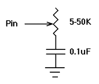
Reads a potentiometer (or some other resistive device) on
Pin. Pins are numbered 0 to 7.The resistance is measured by timing the discharge of a capacitor through the resistor (typically 5K to 50K).
Scale is used to adjust for varying R/C constants. For larger R/C constants, Scale should be set low (a minimum value of one). For smaller R/C constants, Scale should be set to its maximum value (255). If Scale is set correctly, Var should be set to zero near minimum resistance and to 255 near maximum resistance.Unfortunately, Scale must be determined experimentally. To do so, set
the device under measure to maximum resistance and read it with Scale set to 127. Adjust Scale until the Pot command returns 254. If 255, decrease the scale. If 253 or lower, increase the scale. (NOTE: This is the same type of process performed by the Alt-P option of the BS1 environment).
Use the following code to automate the process. Make sure that you set
the pot to maximum resistance.For B1 = 1 TO 255
Pot 0,B1,B0
IF B0 > 253 Then calibrated
Next B1
SerOut 2,0,("Increase R or C.",10,13)
End
calibrated:
SerOut 2,0,("Scale= ",#B1,10,13)
5.25. PULSIN
Pin, State, VarPULSIN
Measures pulse width in 10 uSec units on
Pin. If State is zero, the width of a low pulse is measured. If State is one, the width of a high pulse is measured. The measured width is placed in Var, which can take measurements from 10 uSec to 655,350 uSec for 16-bit variables. If the pulse edge never happens or the width of the pulse is too great to measure, Var is set to zero. If an 8-bit variable is used, only the LSB of the 16-bit measurement is used. Pins are numbered from 0 to 7.Pulsin 4,1,W3 'Measure high pulse on Pin4 and place width * 10uSec in W3 |
5.26. PULSOUT
Pin, PeriodPULSOUT
Generates a pulse on
Pin of specified Period in 10 uSec units. Since Period is 16-bits, pulses of up to 655,350 uSec can be generated. The pulse is generated by toggling the pin twice, thus the initial state of the pin determines the polarity of the pulse. The pin is automatically made an output pin. Pins are number 0 to 7.Pulsout 5,100 'Send a pulse 1mSec long to Pin5 |
5.27. PWM
Pin, Duty, CyclePWM
Outputs PWM pulse train on
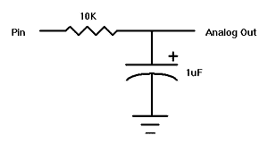
Pin. Each cycle of PWM consists of 256 steps. The Duty cycle for each PWM cycle ranges from 0 (0%) to 255 (100%). This PWM cycle is repeated Cycle times. Pins are numbered from 0 to 7.The pin is made an output just prior to pulse generation and reverts to an input after generation stops. This allows a simple R/C circuit to be used as a simple D/A converter:

Pwm 7,127,100 'Send a 50% duty cycle PWM signal out Pin7 for 100 cycles |
| <<Previous |